One of Max Mosley’s lasting legacies in F1 was the introduction of his vision of a green initiative in F1. As a result KERS (Kinetic Energy Recovery System) was introduced 2009, as part of a greater package of rule changes to change the face of F1.
KERS is a system which harvests energy under braking and stores it to provide the driver with an extra power boost each lap. A simple technical summary of KERS is here (https://scarbsf1.wordpress.com/2010/10/20/kers-anatomy/ ).
During the 2009 season McLaren were applauded for running Mercedes KERS at every race and it was widely reported as the best KERS in use that year. Along with a few other journalists, I was invited along to Mercedes AMG Powertrains in Brixworth, UK to hear about KERS development since 2009. With Managing Director Thomas Fuhr and Engineering Director Andy Cowell giving a presentation on the range of work Mercedes AMG does with its F1 teams.
Mercedes AMG Powertrains reside on the site that was previously Mercedes Benz High Performance Engines (MBHPE). Now renamed to reflect the wider application of the groups knowledge, both to uses outside F1 and to areas other than engines. Powertrain is a catch all term covering; engine, transmission, electronics and of course KERS Hybrid systems.
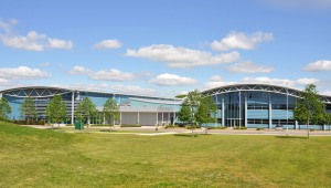
The company have built a purpose designed Technology Centre on the site, which historically was the Ilmor engine plant and positioned just a few miles from Cosworth in Northampton. Clearly this area has a rich seam of Engine knowledge.
Formed around three buildings the entire F1 engine and KERS development is carried out on site, only specialist functions such as the casting of the crankcases is carried out off site. Additionally other Mercedes AMG work is carried out here, such as the AMG E-cell car.
KERS 2009
Mercedes AMG (MBHPE as it was known then) developed their first KERS for 2009 in house. At the time McLaren were the primary customer for the system, although Force India and at the last minute Brawn GP were also customer teams that year. Force India had a chassis prepared to run KERS, but chose not to during the season. Brawn had a chassis designed before their switch to Mercedes engines, so their car was not designed to accept the Mercedes KERS.
In designing the system, Mercedes AMG had a specific requirement from McLaren. As the effectiveness of KERS was unknown, McLaren didn’t want to compromise the car if KERS was removed. So the system was packaged to fit into a largely conventional car. Whereas other KERS suppliers went for a battery position under the fuel tank, McLaren and Mercedes AMG placed theirs in the right hand sidepod. Low down and far forward, on the floor between the radiator and the side impact structures. The battery pack contains not only the array of individual cells, but also the pump and pipe work for its water cooling circuit. As well as the electronic interfaces for its control and monitoring. The assembly is around 7cm high, 12cm wide and 40cm long. The KBP is probably the single heaviest KERS component. In 2009 this sidepod package was acceptable as the teams were still on Bridgestone tyres and seeking an extremely forward weight distribution. Thus the 5cm higher mounting in the sidepod was offset by its forward placement.
Conversely the smaller Power Control Unit (PCU) was placed in a similar location in the other sidepod, ironically the PCU is around the size and shape of road car battery. This left the monocoque uncompromised, aside from the smaller cut out for the MGU in the rear bulkhead.
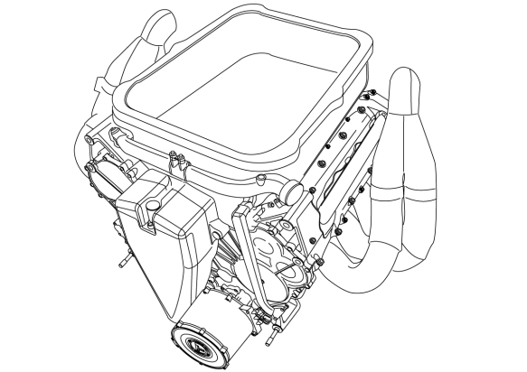
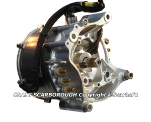
Then the Motor Generator Unit (MGU) is mounted to the front of the engine. This device generates and creates the power for the KERS. Its driven from a small set of gears mounted to the front of the crankshaft. the unit remains with the engien when the car is dismantled and is oil cooled along with the engine.
All of the components are linked both to the SECUs CAN bus and to each other by High Current Cable. The latter taking the DC current between the Batteries and MGU. With this packaging Mercedes AMG quotes the total system weight as 27kg.
Designed and developed by Mercedes AMG, but other partners were involved; the unique battery cells were supplied via A123 and the MGU was partnered with Zytek. Although the power control electronics were solely a Mercedes AMG in house development.
Through the 2009 season both McLaren drivers had a safe and reliable KERS at each race. The system was safe even after crashes and was fault free despite rain soaked races. Safety was designed in from the outset, all electrics were double insulated. Teams can also measure damage to the unit via accelerometers and insulation sensors, so any impact or incidental damage can be monitored and the car retired if the need arises. Additionally each cell in the battery has its temperature monitored. KERS batteries are sensitive to high and low temperatures, each cell needing to operate in a specific thermal window. Too low and the unit is inefficient and too hot and there’s the danger of explosion.
Perhaps the only criticism was the sidepod battery mounting, despite several incidents, this never put any one in danger, so this never proved to be an unsafe installation.
KERS 2011
For a variety of non technical reasons KERS was agreed not to be raced from 2010 until the planned 2013 rules. However this plan changed, but not before Mercedes AMG had made new strategic plans around KERS.
Mercedes AMG set out a longer term strategy to work on research for KERS in preparation for 2013, as well as working with AMG to develop the road car based E-cell technology.
(Link Mercedes AMG E-Cell chassis )
This changed when the plans for the 2013 engine were pushed back to 2014 and KERS was agreed to be reintroduced for 2011. Thus the 2013 development plans had to rebased and deliver a refined version of the 2009 KERS for 2011. Moreover there were now three teams to be supplied with KERS. There was no Christmas for Mercedes AMG staff 2010!
As a result of the research work carried out after 2009, Mercedes AMG now solely design, develop and produce the entire KERS package, aside from the Battery cells. So now the MGU is a wholly Mercedes AMG part.
With KERS effectiveness proven in 2009, it was possible to have the cars designed around it, rather than it be an optional fitment. So the packaging was revised and the entire system integrated into just two units. The MGU remains attached to the front of the engine, still driven off a spur gear on the nose of the crankshaft. While the KBP and PCU are now integrated into a much smaller single package and fitted under the fuel tank. The unit bolts up inside a moulded recess under the monocoque, the unit being attached using four vibration mounts, and then a closing panel and the cars floor\plank are fitted under it.

The 2009 battery pack (yellow) is now integrated with the power electronics (not shown) in a single unit under the fuel tank (red).
It’s this integration of the batteries and power electronics that has has really slimmed the 2011 system down. Mercedes AMG now quote 24kg the entire KERS, much of the 3kg weight loss being down to the reduction in the heavy power cabling between these units.
Not only is the packaging better, but the systems life and efficiency is too. Round trip efficiency stands at a stated 80%, which is the amount of power reapplied to the engine via the MGU after it has been harvested and stored. Improvements in efficiency being in both the charge and discharge phases.
Battery pack life was extended to as much as 10,000km, several times the 2009 predictions that batteries would need replacing every two races (2,400km). Over this period, the cells do not tend to degrade, as the team manage the unit’s condition (‘State of Charge’ & temperature) throughout the GP weekend to maintain their operational efficiency.
The 80hp boost KERS provides, stresses the engine. This was well known back in 2009, but for 2011 along with DRS the car can be several hundred revs higher than the usual EOS (end of straight) revs. Mercedes AMG quoted 15-25% more stress for a KERS and DRS aided lap, this needing to be taken into account when the team monitor the engines duty cycle, thus deciding when to replace it. Mercedes conducted additional dyno development of the engine being kept on the rev limiter to fully understand and counter this problem. This work paid benefits; Hamilton ran many laps at Monza bouncing off the rev limiter along the main straight, while chasing Vettel.
KERS in use
Although the max 60KW (~80hp) output can be reduced from the steering wheel, its normal for the driver to use the full 80hp boost each time they engage the KERS boost. With a reliable KERS, the driver will use the full 6s boost on every lap. Media reports suggest Red Bulls iteration of the Renault KERS does not use this full 60kw. Instead something like 44kw, providing less of a boost, but allowing smaller batteries to be used. The loss in boost being offset by the overall benefit in car packaging.
The driver engages a KERS boost either via a paddle or button on the steering wheel, or by the throttle pedal. The latter idea being a 2009 BMW Sauber development, where the driver pushes the pedal beyond its usual maximum travel to engage KERS. Nick Heidfeld brought this idea to Renault in 2011 and the over-extended pedal idea has also been used for DRS too.
Once the driver is no longer traction limited out of a turn, they can engage KERS. Usually a few small 1-2s boosts out of critical turns provides the ideal lap time. It’s the driver who has to control the duration of the boost, by whichever control. As with gear shift the drivers can be uncannily accurate in their apportioning of the boost around the lap. It’s suggested that the 2009 Ferrari system apportioned the duration of the KERS boost via a GPS map, the driver simply presses the button and the electronics gives them the predetermined amount of boost. This solution came as surprise to Andy Cowell, so one wonders if this is legal or perhaps if the report is true.
From on board shots, we’ve seen the steering wheel has an array of LEDs or numerical displays to show the driver the boost remaining for that lap. The SECU will have control code written to prevent overuse of KERS around a lap.
Typically the battery will hold more charge than a laps worth of harvesting\discharge. So that any unexpected incidents do not leave the driver without their 6s of boost.
In use KERS can be used in several different ways. When lapping alone KERS typically gains 0.45s per lap, although this varies slightly by track. Along with DRS is can boost top speed by 12kmh. As explained the driver uses a pre-agreed amount of boost, decided from simulation work done at the factory before the race. So the planned strategy of KERS usage will be used in practice, qualifying and in parts of the race. However in the race the driver can use KERS tactically to gain an advantage. Drivers are able to use more a KERS boost to either overtake or defend a position. One feature of 2011 along with the Pirelli tyres being in different condition during the race, was the driver’s freedom to alter their racing line and use their grip and KERS to tackle their rivals.
KERS future
KERS continues in its current guise for another two years, then for 2014 along with all new engine regulations there will be a new format KERS. Energy recovery will be from different sources, so the overriding term for the hybrid technology on the car will simply be ERS (Energy Recovery Systems). However KERS will still exist, harvesting energy from braking, but will have a greater allowance for energy stored and reapplied. But, there will also be TERS (Thermal Energy Recovery), which a MGU harvesting energy from the turbocharger. Overall ERS will provide a third of the engines power for some 30s of the lap. No longer will the driver press a button for their KERS boost, it will be integrated in their demand for power from the throttle pedal. The electronics will be constantly managing the Powertrains energy, harvesting and applying energy based on whether the driver is on or off the throttle. In 2014 Powertrains and ERS is set to become very complicated.


Wow – that was certainly a lot to take in, really enjoyed reading it.
And not once in all that did you use the term “KERS System”.
Nice article, Thanks Scarb!
However I wonder how the KERS motor is connected to the drive train. It is connected to the engine and that is connected to the gearbox, or the KERS motor drives directly (with some gears) the crankshaft? This is interesting because both demands completely different RPMs from the KERS motor, and I am sure it has an optimal RPM for giving its peak performance, while charging and while boosting the performance of the car. Maybe there is a small gearbox in the KERS motor?
Don’t forget that maximum torque of an electric motor is at zero rpm.
Thanks for the article Scarb. I wish more teams and suppliers would release technical details and photos like this; they wouldn’t be revealing any secrets to their rivals. Speaking of photos, why is Caterham being so coy with their pictures? I visited their website and all they had posted were b.s. out of focus arty shots of the nose; it’s not like the other teams are going to drop what they’re doing and copy their design – it’s a bit late for that even if they wanted to. I won’t visit their site again.
Mercedes AMG were great in giving us such amazing access. But they were still guarded in letting info out of the factory. They didnt provide these pictures or copies of the presentations. These pictures are my own, from either the Mercedes AMG foyer or the 2009 KERS on display at the F.Student Silverstone event this year.
I agree teams should give more technical access and info, after all F1 is sport about cars and technology, as well as drivers. May be they should be more secretive with the drivers and free up tech access instead?
Great article once again. I don’t suppose Mercedes AMG Powertrains mentioned McLaren’s earlier flywheel work with Ricardo…
I didn’t think Brawn had KERS in 09? I distinctly remember Button referring to Lewis’ overtake button when being interviewed…
@Jon Cooper: BrawnGP didn’t have Kers indeed (and neither Force India had it). I think in the article it is said that Brawn and Force India were using Mercedes-Benz engines in 2009, as well as McLaren, but only the Woking-based team had KERS fitted into their car. Anyway in 2009 the double diffuser proved to be more important than KERS performance-wise.
Thanks Craig for every technical explanation!
Pingback: New Lotus to be called the E20 | F1 Fanatic – The Formula 1 Blog
Great Blog work again Scarbs.
An excellent KERS technical treatement. An Engineers’s tick from me. JF
Great article but…..Some of the information you list for the 2009 KERS system are incorrect!! The power electronics, hardware and software, was developed by Zytek, not HPE. In fact other than the battery pack the entire KERS system was produced and developed by Zytek.Over a period of 18 months three phases of systems where completed by Zytek, from a pure ‘test’ bed unit to the system which was raced by McLaren. Also just to be picky at the British GP in 2009 the KERS system was NOT raced. McLaren felt it gave no real gain, due to the lack of braking events.How do I know this, I worked at Zytek in 2009 on the KERS system!!Spent many a long hour on the test beds with the system.
Maybe you could tell us more, if you can 🙂 But I know it is strange that mostly those people gets all the attention who did no real work, and those who did, are sidelined. Sadly.
Pingback: Launch Analysis: McLaren Mercedes MP4-27 | Scarbsf1's Blog
Pingback: KERS in Formula 1 2012 « Technid